
The Arctic Tracker lab model has a main microcontroller unit (Teensy 3) and a ESP-12 WIFI module. Now, can we connect the tracker to a PC or to the internet (using WIFI) and can we make a web interface to configure the tracker? Yes, it seems like we can. It can connect to the internet, and a simple web interface can be demonstrated, but it can be challenging because the ESP module with NodeMCU is very limited when it comes to RAM. It easily crashes if putting too much load on it. The ESP-8266 was meant to be a IoT (Internet of things) device, not a generic webserver.
A significant amount of code is being written. It is too much to explain in detail here, but it is of course on GitHub. Feel free to look at it to see how it works. There are two repositories:
- ArcticTracker. Source code for the firmware to be run on the main MCU.
- ArcticTracker-ESP. Scripts to be run on the Wifi module (mainly LUA scripts).
First, the WIFI module and the main MCU need to communicate. The WIFI module need to send commands (over the serial line) to the main MCU to access settings or ask it to do things, and vice versa. It is somewhat tricky since both modules need to have two roles: client and server, and they need to switch between these two roles. In addition, sometimes, we may need access to the NodeMCU LUA shell. E.g. in order to upload scripts to the module. At startup, the WIFI module runs a init script containing set-up and functions. The main MCU asks (see code in wifi.c) it to activate a thread that listens on the serial port and processes incoming commands (or responses). This renders the LUA interpreter shell inactive. A special command (“SHELL”) can be sent to the WIFI module to put it back into LUA shell mode (‘wifi shell‘ command in main tracker shell (over the USB line) initiates this).
It is easy to get the WIFI module to connect to an access point by just setting a SSID and password statically. However we want a little more flexibility so we do it as follows: At startup the WIFI module scans for access points and for each found, it asks the main MCU if it knows a password for it (or if it is registered as a open AP). Up to 6 access points can be registered (in prioritized order) on the main MCU. Then the tracker will connect to the first available access point in this list. It can also take the signal strength in consideration, prioritizing close access points over distant access points. The picture shows how we can check this in the main tracker shell by using the ‘wifi info‘ command. The WIFI module can act as its own access point as well. This is good because it will always be an easy way to connect the tracker directly from a laptop or a smartphone. For this to work we need a unique SSID. For now, the chip-ID of the ESP is used, but in a later version we may use the callsign (mycall) instead.
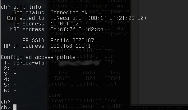
There are several examples of running simple webservers on the ESP8266. Our code is based on httpserver by Marcos Kirsch which runs on NodeMCU. It stretches the module’s capacity to the limit however. The image on the top of this post gives an impression. It shows some information about the tracker. Some of it is information from the main MCU module. This is put in a iframe along with a menu on the left side in a way that uses little resources on the server. In principle, we could add content (images, etc) from other servers as well, but should perhaps not depend on that. I have not succceeded in putting images (graphics) on the page since the server then runs out of memory.
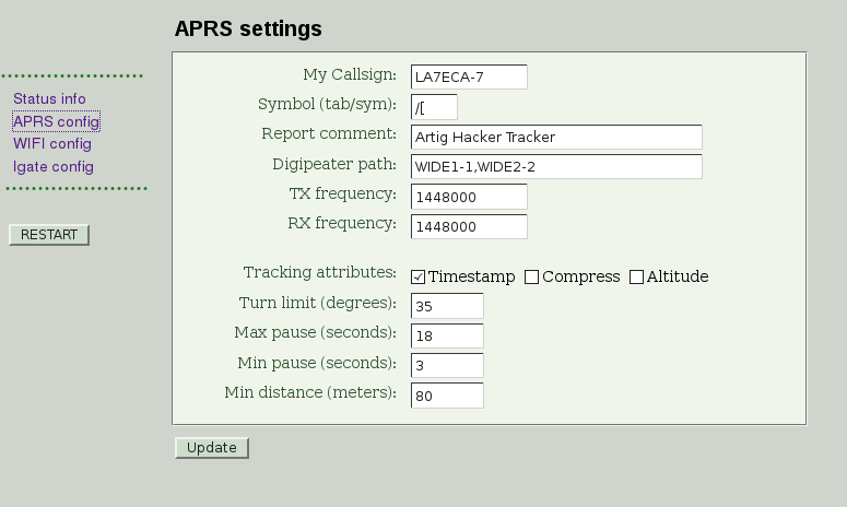
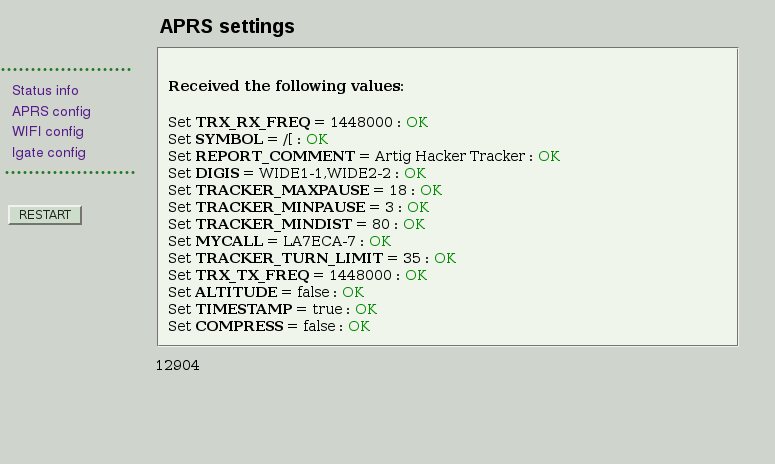
The picture above shows how to generate a web form letting us change the most important APRS related settings. It is generated by a LUA script, getting settings from the main MCU. When clicking the submit (Update) button, a POST request is generated and handled by another LUA script (I had to split the script to save memory). This script sends updates to the main MCU where they are validated and “OK” or “error” messages are returned. This demonstrates how to make a tracker with its own web interface to inspect and update settings. This pattern can be reused for more settings. It is close to the limit of what (with the current implementation) can be done with the module’s memory. If we need more fields than this on a page than shown here, we should consider splitting it into two or it will run out of memory. It remains to be seen if it is possible to save some memory by tuning the implementation, or if new features will eat too much memory. The webserver uses basic authentication, so a username/password would need to be set somewhere.
The conclusion is that WIFI setup works quite well and it is possible to offer a simple webserver for configuration, though with limitations. There are still some open issues. What WIFI mode should we use? It will affect the range and the power drain. Should the WIFI radio be shut down or put to sleep to save power and battery? Could it automatically decide to turn off the WIFI when not needed or should it be done manually by the operator? How can the main MCU use the WIFI module to connect to APRS-IS or other internet services to upload information? Should the webserver be shut down (automatically or manually) to save power or to leave more memory to other activities. This remains to be explored in further work.
The ESP-32 is a sucessor of the ESP-8266. It has more RAM, a more powerful dual-core CPU and a lot more I/O pins. Then it is likely that this chip can do the job without needing another MCU. However, it will require some work to port software to this new platform. We will follow this with interest and maybe a later version of Arctic Tracker will use the ESP-32.