
Arctic Tracker is both a hardware and a software project. Until now, hardware has mainly aimed to demonstrate how to make trackers from affordable modules, in particular the ESP32, and relatively few discrete electronic components in addition. The ESP32 is a popular and fairly advanced microcontroller. It has been used in several products aimed at makers, education, and radio-amateurs for instance.
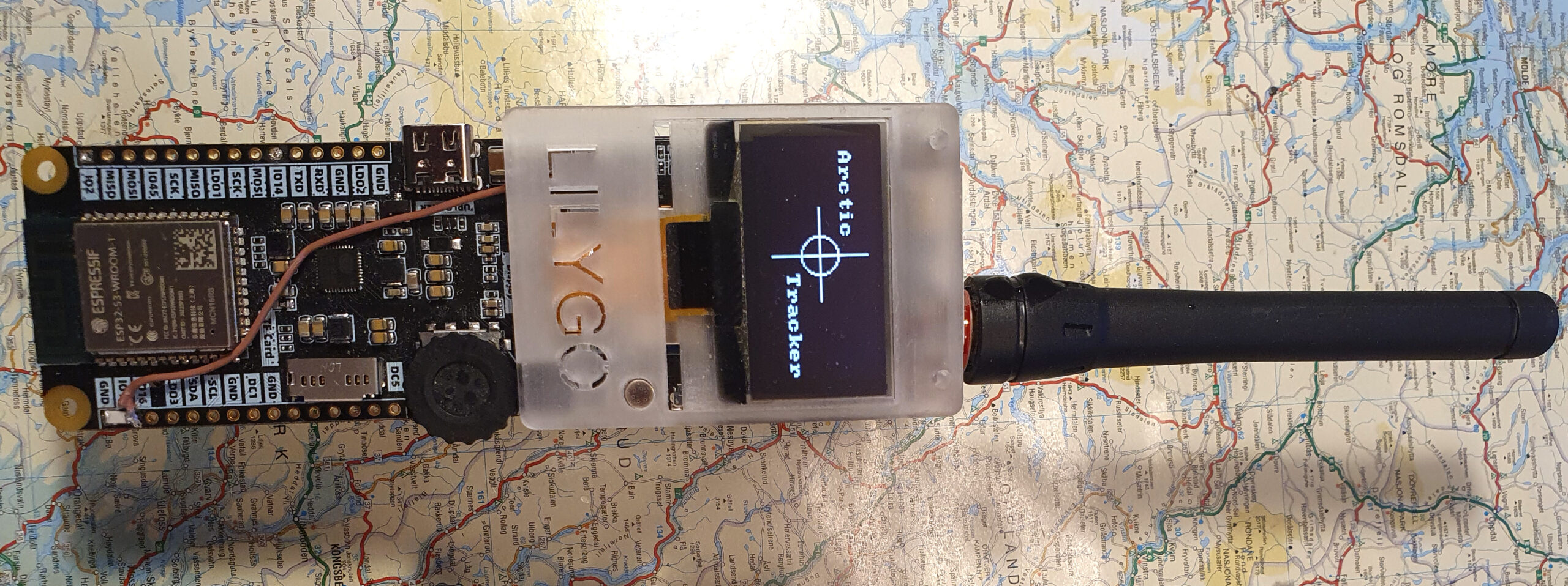
LilyGo offers a series of open source hardware boards, many of them using the ESP32 and many of them with a radio module (typically LoRa), a GNSS module, etc. One particular board is the T-TWR-plus. Coming with a VHF or UHF radio module, a GNSS module, a ESP32S3, etc. It can be used as a voice-radio, even a digital voice radio (with M17) as done in the OpenRTX project, but also as a APRS tracker as done in the ESP32APRS project. The T-TWR has many similarities with the Arctic Tracker prototype, so I got a question if I could be interested in porting the Arctic Tracker software to it. So after some hacking, here it is.
The Arctic Tracker software is open source and has a GitHub repository.
Hardware modifications
Note: From version 4.0 of the firmware, a software squelch allows the squelch to be open all the time.
I did one modification to the hardware. I put a wire between the squelch output of the radio module and a GPIO15 of the ESP32. A 1nF capacitor was also put between the GPIO pin and a ground pin in case of RF pickup though it is probably not strictly necessary. In the upcoming version 2.1 of the T-TWR-plus there will be a built-in connection from the radio squelch signal to the ESP32. The original Arctic Tracker had a buzzer and it is an option to put such a buzzer on a suitable GPIO output pin also on the T-TWR. Using the speaker is not a good idea since it is connected to the radio audio output (through an amplifier). Actually, I pulled out the plug to the speaker.

Software modifications
The software is able to run on the ESP-32-S3 and the display rather easily since it is in many aspect the same platform. Just change the I/O pins configuration (main/defines.h). I was able to get it running with the command-shell right away. Now the work could start.
First it was necessary to take control over the Power Management Unit (PMU), an AXP2101. It controls the charging of the battery with power from a USB-C and can deliver several voltages to different units on the board. The chip can be controlled by software through the I2C bus. After some searching I decided to use the XPowersLib. It is implemented in C++ but it is straightforward to make the functions available to the C-program with simple wrappers and to use the I2C to access its registers. Now I could turn on the necessary voltages to the GNSS, the radio, etc. and set up the battery-charging. It can charge with up to 1A, but at max current it is recommended to put a heatsink on the chip. I set it to 700mA. I also hacked the code a bit for showing battery charging status on the display. The AXP chip can give the percentage in addition to the voltage itself. It seems to work very well and I consider using it in my own projects as well.
The radio is a G-NiceRF SA868. It is quite similar to the SR-FRS-1 used in earlier versions; the AT commands are mostly the same, so I just copied the code, made some modifications and did some debugging and adjustments in addition. The generation of audio (using a GPIO with sigma-delta modulation) could be used without modifications. I had to fix some issues with reading the ADC input and the interrupt handling to get the receiver to decode packets. The T-TWR uses ADC1 which is better than using the ADC2 with I used before. The ESP-IDF has a new driver for the ADC so I had to adapt a bit. In future version I’ll get rid of the legacy driver and see if I can use the continous ADC mode. It would probably be more efficient and precise. The unit I tested with seems to have some issue with the RF-sensitivity of the receiver, but yes, it decodes packets. I may look more into it when I have time.
The T-TWR uses a Neopixel multi-colour LED. I found a library (component) with a driver for Neopixel-led-strips. It was used and I was able to use different blinking with different colours to indicate when it is transmitting (bright red), when it is on USB and charging the battery (pink blinks), etc.. The T-TWR also comes with a rotary encoder. It uses three inputs but it is not just like three buttons. You need to decode the signals from it to find what way it is rotating in a reliable way. After some reading and some testing I finally got it working by implementing a proper state machine. The rotary encoder works nicely for cycling through the different screens of the display or the menu items.
User interface – display
The UI (the display) lets the user cycle through 8 screens, including the intro-screen with the logo, using the rotary knob. 4 examples are shown below. If you push and hold the button (or the rotary knob) for about one second, a menu will pop up offering opportunity to turn things on and off, etc.. You can also use the top button instead of pushing the rotary knob.
The current screens are: APRS (callsign, frequency, digipeater-path and number of reports sent), GPS (the position), WIFI (info about connection to an AP, IP-address and hostname), W-AP (softap if activated), BATT (battery charging-status), SYST (system-info) and TRKL (track-logging status).
The top of the screen shows which screen is selected, the battery-status and some flags: i=WIFI-connected, d=digipeater-on, g=igate-on, c=charging-on.

Console (command shell)
The Arctic Tracker offers a serial console (command shell). This lets you control every setting and has some commands for testing, debugging, etc. It is a useful tool when developing. It is recommended to use it the first time you start the tracker for setting the wifi access point and access-key. When you plug in a USB-C cable and connect it to your computer a serial interface should appear (on Linux it is /dev/ttyACM0). A good old serial terminal program will probably work. You may need to reset the tracker to get up the command prompt (cmd>).

The ‘help‘ command gives you a list of available commands. ‘help <command>‘ gives a short explanation of the given command. Be sure to set the callsign (‘mycall‘). The ‘tracker on’ command turns on the tracking function. ‘radio on’ command turns on the radio. The ‘wifi on’ command turns on the WIFI. The ‘ap’ command lets you set up a list of WIFI access points. The tracker will try to connect to these in order if they are in range. If the first one fails, it will try the next. Also, before you try to use the webapp, use the ‘api-key’ to set a secret key to be used for the webapp to authenticate. ‘api-origins’ should be set to a regular expression matching the origins expected for the webapp. “.*” (dot star) will match all. If things are working as expected, you should also be able to get to the most important settings with a web-browser.
Webapp and REST-API
Arctic Tracker comes with a HTTP server and a REST-API, allowing it to be configured or controlled from a smartphone or a PC. When it is connected to the internet with WIFI, you can access it from your web-browser. The webapp lets you manage multiple trackers. Your browser should be on the same LAN as the tracker. Then you can just enter the callsign (if it is configured) as the tracker-id, its API-key (if it is configured) and add it. Then it should be able to find it. If it is found and authentication is ok, the callsign label becomes green. When you have got access to one tracker, it can automatically discover other trackers on your LAN using mDNS (Zeroconf).

When a tracker is connected and selected, you manage various parameters using the widgets: Status, Wifi, Aprs, Digi/Igate and TrkLog. The next picture shows digipeater/igate setup. It is probably a good idea for a portable digipeater to have the Wide-1 setting on.

The webapp is somewhat work-in-progress. It may also be a good idea to make a smartphone app. A challenge is that to be able to access IoT devices like this from web-browsers in a secure way we need to use https (SSL/TLS). This requires the trackers to have a X.509 certificate and a corresponding private key. Currently we use a self-signed certificate which is embedded into the code. This means that before we can access the REST API of a tracker we need to connect the tracker directly from a web-browser and tell the browser to accept an exception for its certificate. The tracker contains the webapp. First time you use it, just point your browser to it (the IP-address and hostname is shown on the display).
The Trklog is currently not quite ready; the idea is that the tracker can store positions on the flash-filesystem and upload them automatically to a server (Polaric Server has implemented this) when it connects to the internet. More on this feature (and other cool features) soon. Stay tuned!
73 de LA7ECA
Comments
4 responses to “Arctic Tracker software on LilyGo T-TWR plus”
This looks amazing.
I notice the readme doesn’t mention how to flash the release binary to the T-TWR Plus. Is it as simple as just using the Flash Download Tool and sending the binary to the device at address “0” like the original firmware, or is there more to it than that?
Hi, Jim.
I admit that there should be some info on how to flash the firmware. I will try to add some more info to the readme soon. The binary contains the partition table and the webapp files in addition to the app itself. It can be flashed using the esptool.py which comes with the esp-idf, but I believe other flashing tools would work from address 0. I do not know all tools out there – I use esp-idf myself to build and flash it. As far as i can see, the OTA upgrading works.
It is possible to flash it by converting it to UF2 format first and flashing using a UF2 bootloader. Here is one example from lysusopov:
$ uf2conv.py /tmp/ArcticTracker-3.1-rc1.bin -c -f 0xc47e5767 -b 0 -o /tmp/ArcticTracker-3.1-rc1.uf2
How does one flash from the pre-built binaries? I tried flashing just the binary and got a boot loop.
See the other question above. If you get a boot loop, can you see what is the output to the console? It can give a clue what is going on.