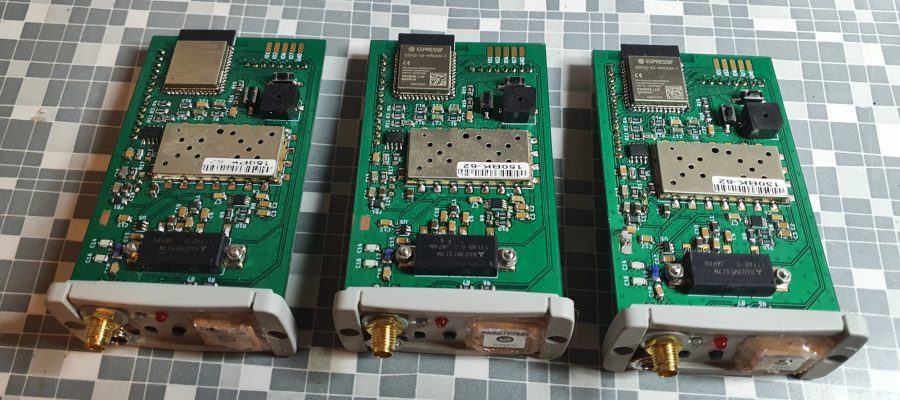
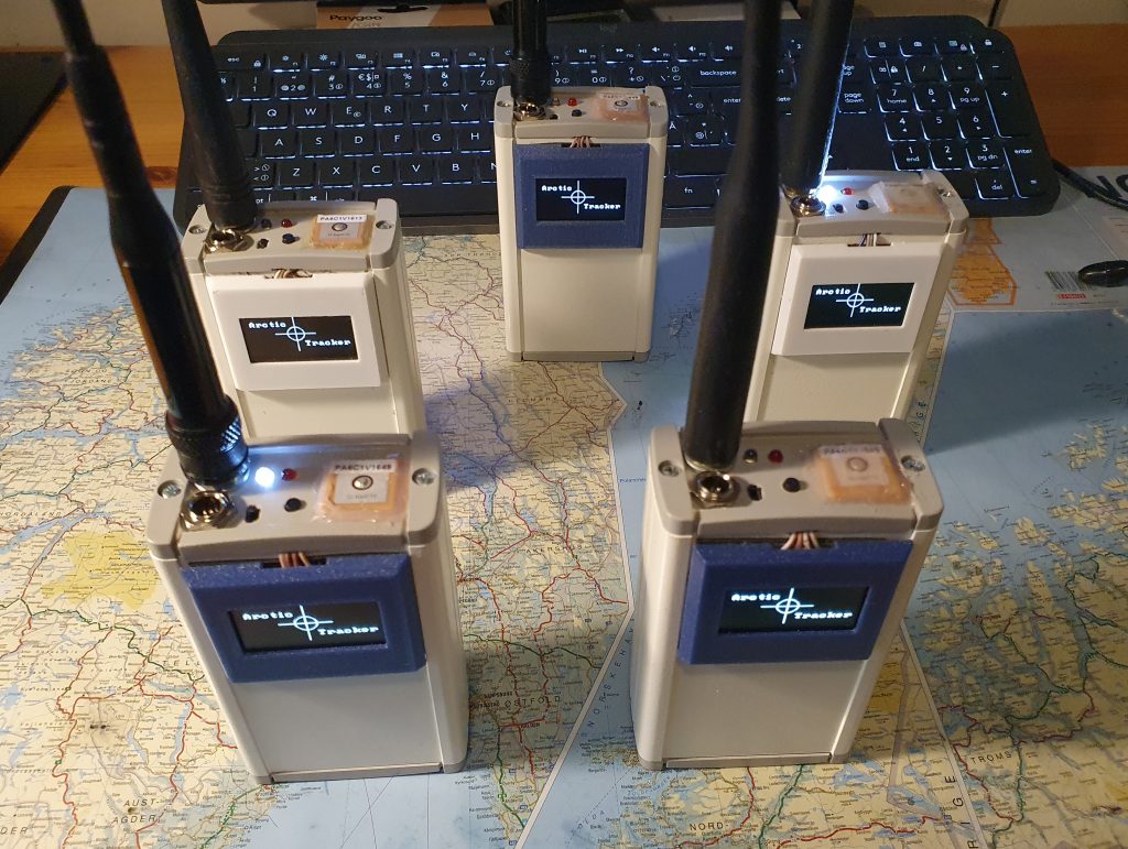
Five tracker prototypes have been made in this round. As described in the previous post, this third version is based on the ESP32-S3, it has a USB-C socket and a OLED display on the outside of the enclosure, with a 3D-printed cover.
Display
The first idea was to replace the Nokia LCD display with a 0.96″ OLED display based on the SSD1306 chip. It has a 128×64 pixel resolution, but it is rather small, so I found a replacement which is 1.3 inch but based on SH1106. It is compatible…, well, almost: A small hack in the firmware, shifting the pixels to be displayed a little did the trick.
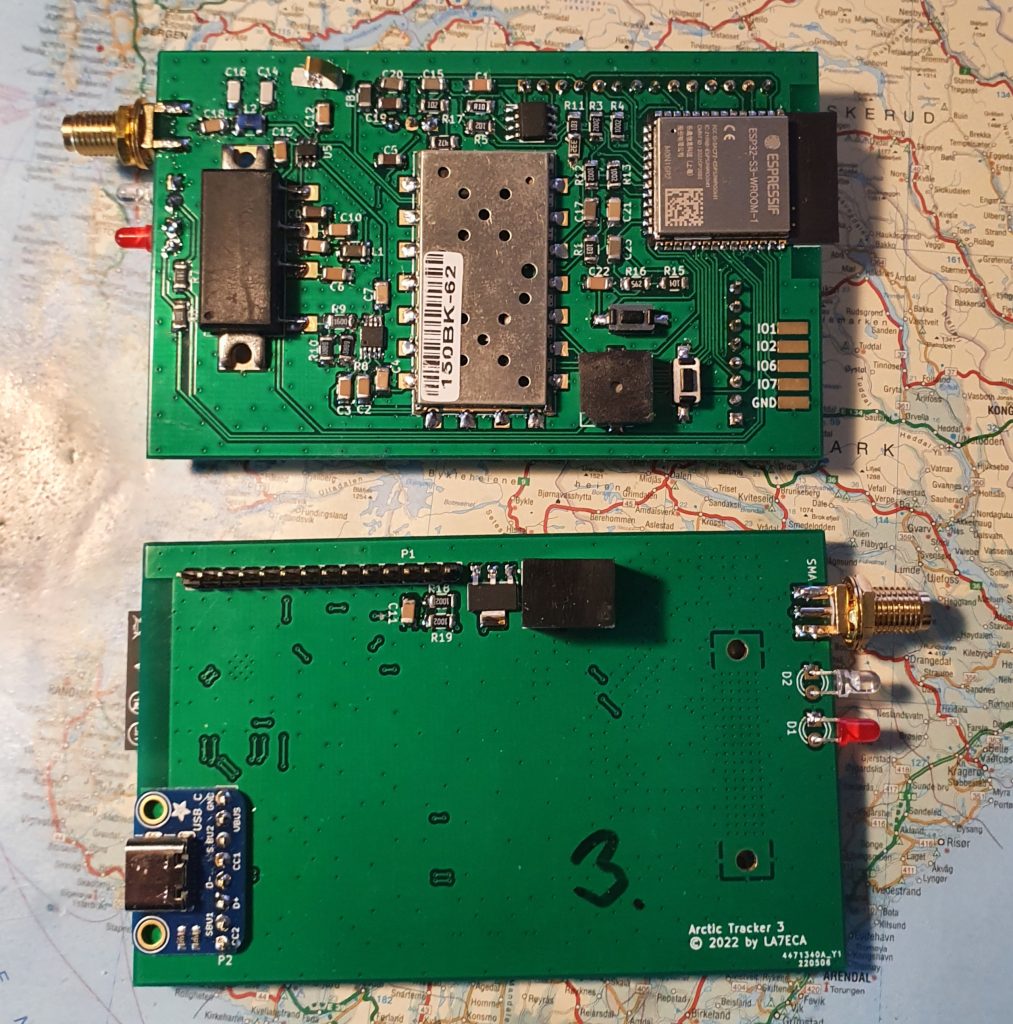
Microcontroller module and USB socket
This version is based on the ESP32-S3. The modules used comes with 2MB extra RAM and 16 MB flash. The extra memory comes almost for free and gives plenty of space to play with. The ESP comes with USB interface and that is really a good thing. I only needed a socket for USB-C and a quick and easy way is to use a breakout board. It is easy to solder to the PCB and is robust. There are a lot of cheap breakout boards available and I used the one from Adafruit. I currently don’t use the USB-C for charging or power supply though. Maybe I should? Next version? The USB is used for programming and for the serial command shell. When you plug the tracker into the computer it comes up with a virtual serial interface.
Version 2 had some issues with setting the ESP in bootloader mode, I therefore added two small buttons to the PCB. One reset (pull down the EN pin) and one to activate the bootloader mode (pull down IO0). This is actually the same IO pin as the button on the front. In addition, using the USB interface (used the IO19 and IO20 pins on the ESP), also made programming much easier. All is done by the script on the computer that comes with ESP-IDF. I have only used the buttons once to force it into programming mode. In most cases you don’t have to worry about this. This is a convenient design.
The S3 has lots of IOs. For future experimenting there are two spare GPIOS on the P1 socket and 4 pads with spare GPIOs on the PCB above the USB socket. The UART ports are used for communicating with GPS and radio module. I2C is used for the display and is only 4 lines including power and ground.
Charger circuit
A BQ2057WSN is used for charging, along with a transistor. The STAT output of the regulator is used to tell the microcontroller the charging status, however, the voltage here is just the input voltage and that would destroy the microcontroller. Therfore a small modification was needed. An extra resistor – voltage divider. The software can detect if it is charging and show this on the display. A critical component is the sensing resistor since it determines the charging current. A formula for calculating this is included in the datasheet. I discovered that since the charger is LDO it can become pretty hot depending on the input voltage. It should have been designed with better cooling. A cooling fin on the transistor may help. It was also necessary to add a small resistance (0.06 ohm is sufficient) in series with the battery. I increased the sense resistor to about 0.1 ohm to limit the current to 1A and I recommend that the input voltage for charging is less than 10V. 9V is fine. I know this can be somewhat inconvenient if you want to charge using 12V or more, but it is a prototype and a switching regulator would be better in a revised design. The whole thing would also be easier if we could use just one cell batteries instead of two-cell batteries. The use of a PA module complicates things.
Radio transceiver and PA
This part is mostly like before. However, the ESP32-S3 do not have a DAC, so we use the sigma-delta modulator. This requires the audio signal to be filtered. The input RF switch used earlier was really too small to be soldered by hand. We now use another one that is easier to mount and have sufficient isolation. It is maybe pushed to the limit wrt input power since the radio module produces 0.5W. But it seems to work nicely and the tracker produces 5 watt RF output.
Note that the transmitter may interfere with the display so that it crashes when transmitting. A ferrite bead on the display PCB (power supply line) seems to fix this issue. Also make sure that the main PCB ground is connected to the enclosure and maybe also use a counterbalance on the antenna. A spring is placed on the PCB for that purpose of grounding the box.
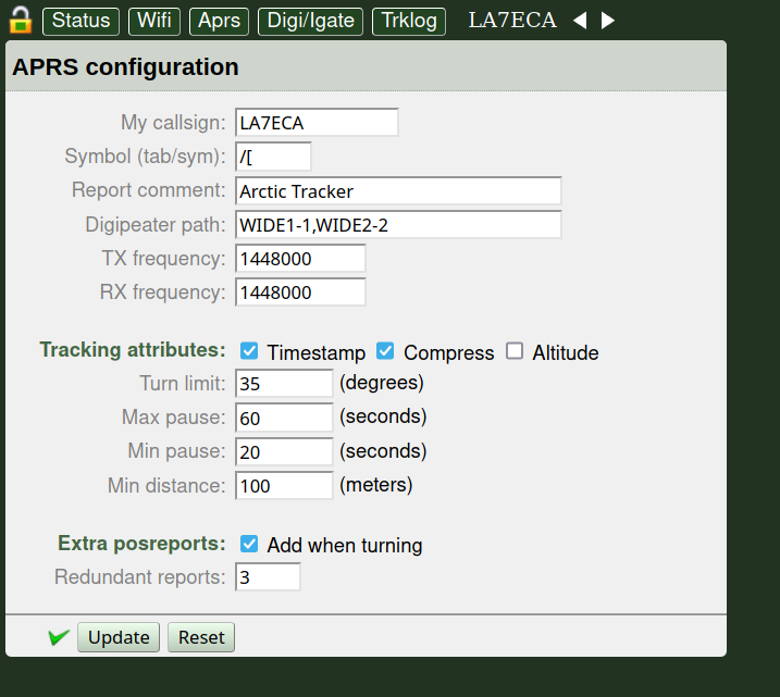
Software
Whats really defines this tracker and what is it main strength, is the software. It is developed in C, using ESP-IDF. The code is free/open source and is on Github. Some features worth to mention (in addition to basic tracking) are:
- A rich command shell (through the USB) support configuration, debugging, testing, etc.
- A REST API for configuring has been made. It replaces the web-pages. It will require an application on a computer or smartphone though but is more flexible. The REST API also have a high level of security, using SHA256 HMAC authentication on REST calls.
- MDNS discovery.
- Digipeater and igate.
- Ability to store posititon (in flash memory) rather frequently (e.g. every 5 second) and when tracker is in range of a WIFI-LAN it can securely upload to a Polaric Server using a REST API.
- Firmware update using the internet (wifi).
Schematic
If someone wants to build this tracker or use some of the ideas tested here, fine. I that case, I will be happy to hear about it. Code and Schematic is Copyleft (GPL).