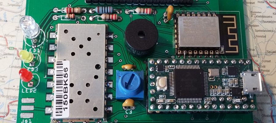
The picture above shows the PCB for the Arctic Tracker with most parts mounted. It was straightforward to solder the parts on the board, except the Teensy. It can be tricky since it need to have 37 pins soldered on it first, and these should either be soldered onto the PCB either directly or a kind of sockets could be mounted on the PCB to allow the module to be plugged in or removed (which is convenient when testing). Soldering pins on the Teensy should be done with care and it is risky to try to remove them afterwards. I damaged a Teensy module after breaking some of the pins and trying to remove them.
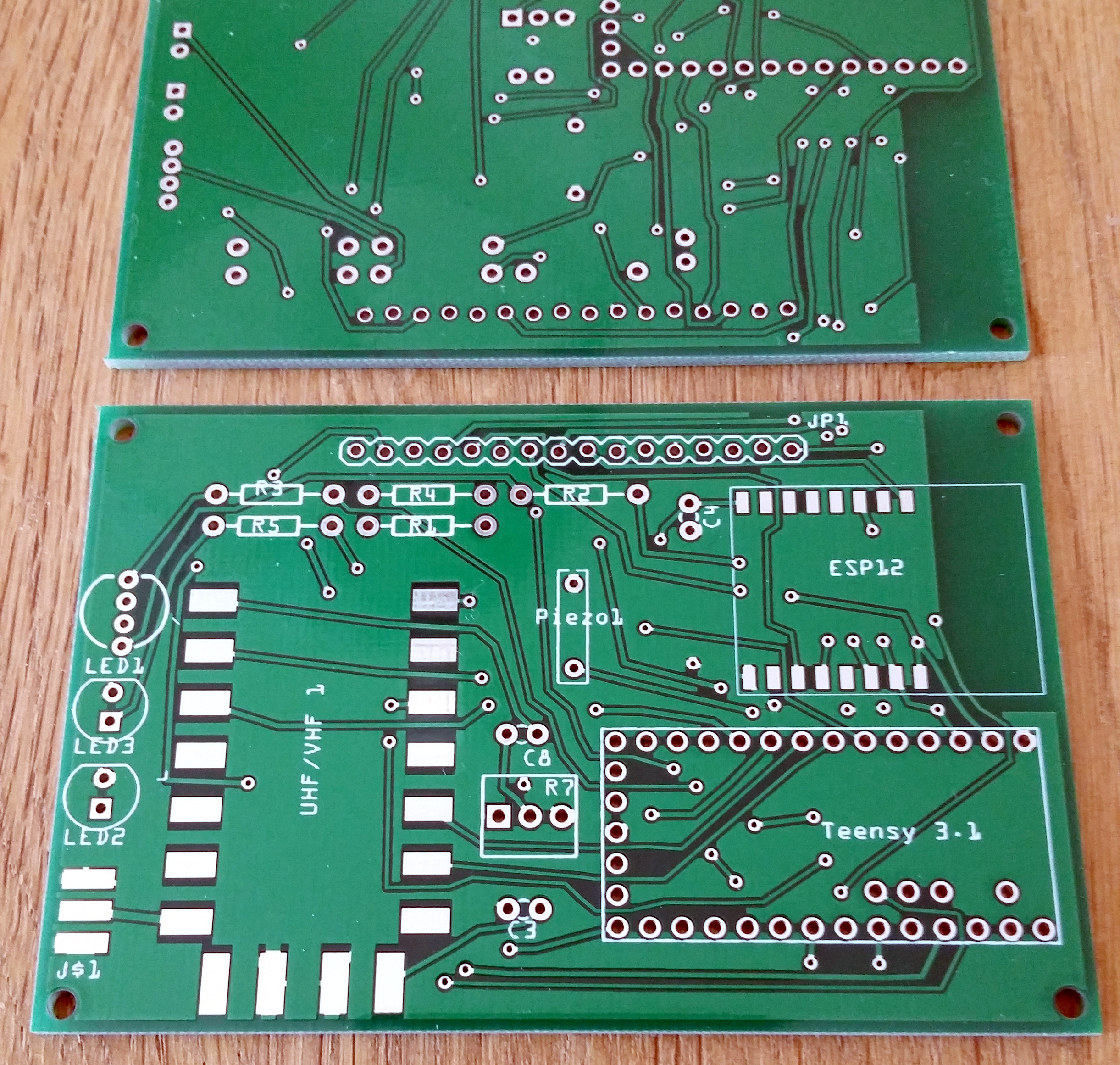
There are several easy (just upload a file) and cheap PCB manufacturers available nowadays. Our PCB was a simple two layer PCB designed with Fritzing and manufactured by SeedStudio. The result seems to be ok. The picture below shows the PCB without parts:
After connecting and flashing the Teensy (the Teensy has its own USB plug and can deliver power to the ESP), the LEDs are blinking, the buzzer is buzzing. Yeah.. I believe it works.
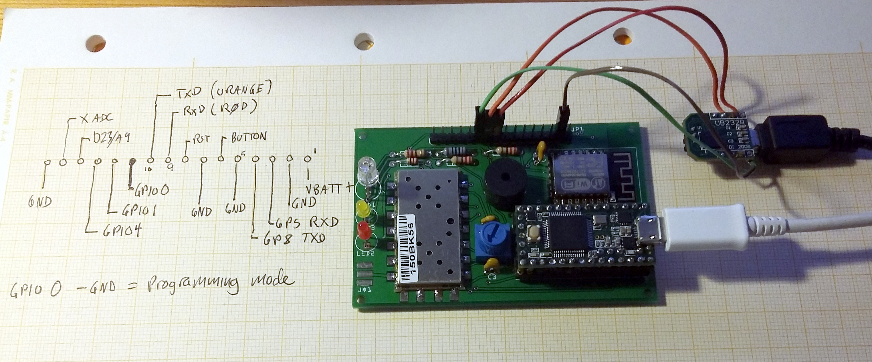
Now, it is time to get the ESP-12 up and running. First, we need to flash it with the NodeMCU firmware. To facilitate programming some pads on the ESP is connected to the pin header JP1. In addition to the serial port TxD and RxD (which is also connected to a serial port on the Teensy), we need the GPIO0 pad. This need to be shorted to ground to enable programming mode. What I actually forgot is that another pad, GPIO15 also need to be grounded to enable programming mode. The was easily fixed with a soldering bridge on the PCB (is is ok to short GPIO15 permanently). Then I could connect a USB/serial converter to the PCB (like in the picture below), reset the whole thing, build a NodeMCU firmware and flash it (with esptool).
After a couple of tries it worked. Now, since the ESP is primarly meant to be accessed from the Teensy MCU, we added another command to the firmware running on the Teensy to re-route the shell there through a serial port to the LUA shell on the ESP. This makes it easy to work with, using the main command shell on the Teensy. It can actually be accessed directly via JP1 and the via the Teensy at the same time. Cool! And useful when developing and uploading data and scripts.
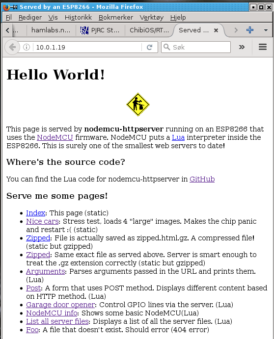
The next step is to try to get it to connect my WIFI access point. Then to run a webserver on it. Believe me, it is possible though the amount of memory on the ESP limits what you can do with it. There are some examples out there. I used the httpserver by Marcos Kirsch. which is a rather complete example. It was edited to use my own WIFI SSID, username, password, etc.
Using the nodemcu-uploader program I could upload files. It actually works best using the direct serial connection via JP1, but yes, after some trial and error I was able to upload files. Actually, the nodemcu shell is not very usable as a command shell; it is just interpreting lua code, so tools like this are convenient. The webserver example is set up with a init file (init.lua) that is run automatically when the device starts. I restarted it, started the shell and observed that it connected to the WIFI network, got an IP address. It even compiled the lua scripts automatically. I could then start the webserver, and take a look with the webbrowser on my PC, and yess…
Now there is more work to do: Learn more about LUA programming, write more code..