The Arctic Tracker was an attempt to create an advanced APRS tracker with modules, and in particular with a Wifi-module, that can be constructed by hand be amateurs. It has proven to work though there have been some issues. Now there is also a work going on with developing a Polaric Tracker 2 in the Norwegian Radio Relay League for “mass production“. It gets some ideas from the Arctic Tracker (based on ESP32, etc.) but also has some innovations of its own. It will probably use much of the software from Arctic Tracker.
So what about Arctic Tracker? It could still be developed more as an experimental platform and maybe a kit for hand-building. It has been described in previous posts on HamLabs. The complete scematic and the PCB could be released but has some flaws just now. If we go on with new version, some issues need to be adressed.
Display and enclosure
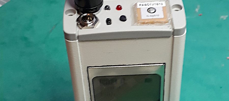
When it comes to the display, it was not a good idea to use the Nokia display and make a hole on the front of the metal enclosure. The text on the LCD screen was nice and readable, even in sunlight, but drilling a hole is tricky and most importantly, there was too little room in the box and tricky to push the PCB, the battery and the display into the box without breaking anything.
On the other hand, the 0.96″ OLED display based on the SSD1306 chip is extremely popular, cheap and easy to get. It has a 128×64 pixel resolution, but it is small – the text is smaller. It is usually blue color and may not be visible in strong sunlight, but I believe we can live with it.
It is already implemented. I was able to re-use some of the code originally made for the Nokia display and make it configurable. Now it is possible to choose what display to use: Nokia display with 84×48 pixels or SSD1306 display with 128×64 or (a smaller version) 128×32 pixels. There is an even smaller version that probably will be used in the Polaric Tracker 2.
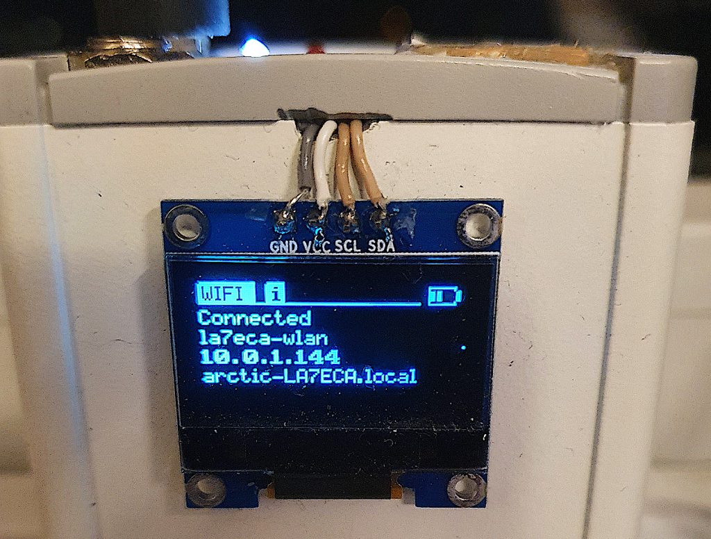
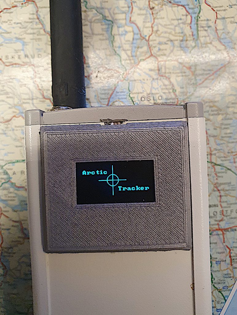
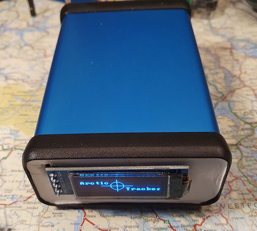
The original font is nice, but I added a bold font and maybe I add a possibility to render text to double size later. The result so far is not bad and display can be sticked to the outside of the box.
With its small size, I2C and just four wires we don’t need to make a large hole to put it inside the box. Now, it would be nice if we could protect the display somewhat by having some kind of cover. This can be 3D-printed to exactly fit the display (thanks to LA3DTA Per for help with 3D-printing). With some small adjustments maybe, this shouldn’t look too bad?
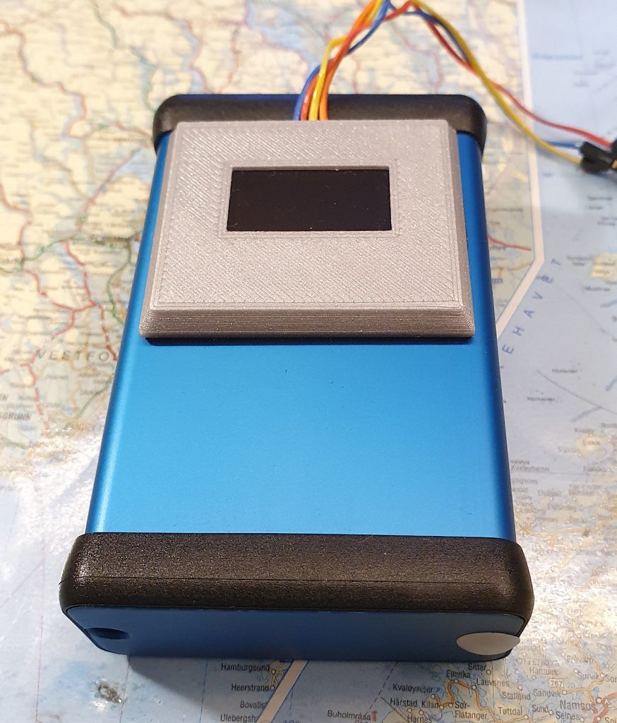
Another alternative is to use a smaller display and stick it to the bottom of the tracker. This could be done with the original enclosure, though I am also considering a smaller one (Hammond) for future versions. I’ll come back to that later. With a smaller enclosure, it is still possible to stick a 128×64 pixel display to the front as shown in the image to the left, but maybe there is another way. Actually a 128×32 pixel display isn’t that bad. It could be put at the bottom, possibly with a 3D-printed cover.
Transmitter and PA
A transceiver module was used. It comes in two versions 1W (SR_FRS_1WV) and 0.5W. The 1W version is easier and cheaper to get hold of and is sufficient in many cases. A PA was designed (using the RA07M1317M module) to boost the output signal to about 5 watt. It also had a lowpass filter between be PA and the antenna. The problem was the switching between receive and transmit. In receive mode, the signal should go around the PA module, it transmit mode it should go through the PA module. To get sufficient isolation (minimize feedback), I used two switcher chips and I used a chip on the input to the PA (F2972) that was only available in 2×2 mm packages. It is too difficult to solder properly by hand. If the goal is that amateurs should be able to build Arctic Tracker by hand, this is obviously a design flaw. However, alternatives now seem to be available. In a next version (if made), I will probably use the PE4250 from Peregrine which is still small (3x3mm) but probably easier to solder by hand.
The PA is the reason why we use a two-cell battery to get sufficient voltage to the PA (7-8V) . It is possible to use a voltage booster, but it is more complicated and the components seem to be hard to get nowadays. An option for a future version is to skip the PA and settle for 1 watt maximum output. This allows for a smaller battery (one cell), and thus a smaller size of the whole thing.
Programming, console and newer ESP32 versions
Even if we can use OTA (firmware upgrades over the internet) and the web-inferface we still need to program it using the serial port, and I believe that the command line console still is very useful to do initial configuration, testing, etc.
A serial port was routed to a 3.5mm jack socket on the PCB, but this is easily broken loose so that the PCB is damaged. So, it must be glued to the PCB. Also I forgot to add a button or a line from the serial port to initiate programming mode. This makes it somewhat tricky to program and should obviously be fixed in a future version.
Since this project was started, new ESP32 modules have been released. The ESP32-S2 has USB but has slightly less internal memory, is single core and no Bluetooth which is probably not a big deal. I cannot see any S2 modules (at this moment) with more than 4MB flash but some of them comes with extra PSRAM. The ESP32-S3 have it all. USB, Bluetooth, dual-core CPU, and modules typically comes with extra PSRAM and have more options when it comes to in-module flash. However it doesn’t have a DAC. I have tested a S3 (Devkit-C) with 8MB flash and 2MB extra PSRAM. Modules exist with up to 32MB flash and 8MB extra RAM. Now we are talking!
Future versions will probably use the S3 and its USB port for programming and console. An external DAC used via I2C or I2S might be an option, though the Sigma-Delta modulator is probably the easiest solution for AFSK generation. I have done some testing and it is straightforward to do in software. It will need a proper low-pass filter though. A two-pole RC filter does the job if the clock is set high enough. USB-C sockets may be somewhat difficult to solder by hand, so I consider using a breakout PCB (e.g. from Adafruit) to simplify it.
Battery charging
The Arctic tracker used an external charger and a socket for this on the top. But few chargers for two-cell LiPo batteries are available on the market. I found one that works. It a next version it would be nice to have a charger circuit on the PCB board to make it more safe and easier to charge with varying input voltages. One option is the BQ2057WSN (used with a transistor). There is also a variant of this chip that supports one-cell batteries. There are also charger breakouts with USB-C plugs available.
Other options for radio
I would be interesting make a version with a RFM98 (or similar) module which is operating on the 433MHz band. A 1 watt version of the RFM98 module is also available. It supports the LoRa modulation. LoRa APRS is gaining popularity amongst radio amateurs and the modules also support FSK, OOK, etc. These modes would probably be more effective than AFSK for carrying APRS packets, so it is worth trying. Some trackers have already been made by Austrian hams for LoRa APRS, based on the ESP32. Very interesting indeed!
Add: There is a component supply crisis going on. So, some components are hard to get, and may have up to a year production time from now. I have for example seen that main stores are out of the most popular (I2C) DAC chips and the price for getting those from those in China still having some, has more than 10-doubled. Crazy!
The source code for the Arctic Tracker firmware is available on Hamlabs Github.
A PCB for a version 3 is made, and is being tested. It works.