
The second iteration of the Arctic Tracker is based on an ESP-32 IoT module (a sucessor of the ESP8266). It is quite capable and still rather cheap. It has Wifi, Bluetooth, a dual core CPU operating at up to 240 MHz, 520 KiB RAM, and several other interesting features. We use a ESP-Wroom-32 module with 16MB flash.
Hardware design
A revised PCB (two layer) has been made, using mainly the same components except that the Teensy and the ESP-12 was replaced with an ESP-32. Since the ESP-32 do not have a USB port, but three serial ports, one of them was used for command shell through a 3.5mm jack and an external USB to serial converter. This is probably ok since the command shell will seldom be used for other than development (configuration and firmware updates can be done using a Wifi connection).

We still use a Nokia LCD display, SR-FRS-1 radio module and a Mitsubishi PA module but the PA circuit is improved by using RF-switch modules instead of PIN diodes for switching between transmit and receive. These are designed for higher frequencies and have high isolation and very low current draw on controlling signals. However, they are small in size (U2 in particular) making them more tricky to solder on the board. This choice, along with better grounding and placement of components around the PA module makes it stable and it works well, producing 5-6 watts RF output depending on the battery voltage.
Software
The software is written in pure C using the ESP-IDF and associated tools, which is again based on FreeRTOS. The code written earlier the Teensy microcontroller in Arctic Tracker first version was based on another RTOS not unlike FreeRTOS, and therefore relatively straightforward to port. Some code (controlling the Wifi, Webserver, etc.) had to be written more from scratch but there are many examples out there. We also use a nice Webserver framework (libesphttpd) which comes with a simple HTML template mechanism. The code is available on Github.
Current status
Currently the following is implemented or ported. And tested:
- Command shell.
- Settings of various parameters, using persistent storage (flash).
- Firmware upgrades over the air (OTA).
- Internetworking using WIFI. Automatically connect to access points available. User can set up an ordered list of APs to try. It can also function as its own access point.
- Webserver. Currently used for configuration of Wifi (access points, etc), Basic radio and APRS setup, Digipeater/Igate and Firmware upgrades over the internet.
- LCD display, button handler, etc..
- Controlling radio and PA module
- Sending and receiving APRS packets
- Interface with GPS and APRS tracking.
Digipeater and Igate code is ready to be ported from the earlier version. In addition we could do some work in reducing the power drain to save battery. Another planned feature is storage of tracks and uploading to the server when internet is available.
Testing
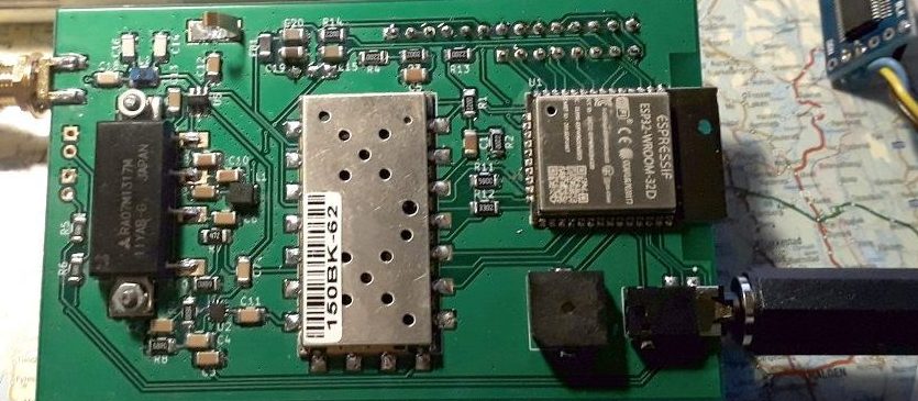
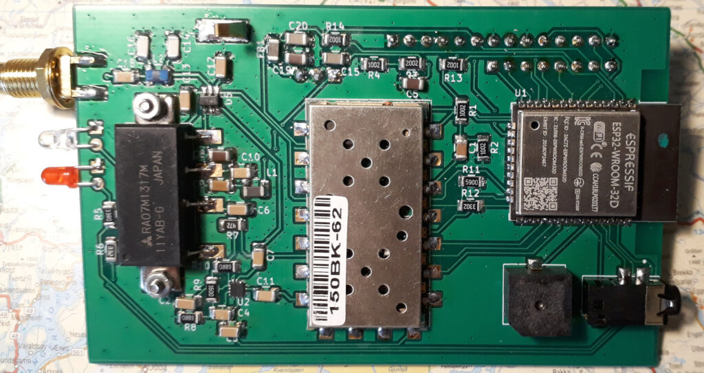
Just like what we did with the first round, a complete tracker was made. Mainly in the same way with GPS, display, two single colour LEDs, a button and a switch on the top. The pictures below shows some of the work. Tracking has been tested and it has been shown that it works and battery last for about 12-15 hours when driving in a car.
There may be one issue with the battery charging though, probably due to the protection circuit in the battery (it is LiPo). The charging voltage is 8.4V nominally and there are cheap chargers available with that voltage, but when the battery is low, we may need to reduce it to 8.3 or even 8.2 or it won’t charge.

PCB with battery, display and top lid. Ready to be put in the box. 
Glueing GPS, switch, power plug, etc. to the top lid. 
Finished tracker prototype
A small error was made forgetting to feed the receiver signal into the ESP-32, but it is easily fixed by adding a short wire. Other possible improvements of the hardware design include the possibility to bypass the PA-module completely from software (0.5w and 1w option), a switch for serial port programming mode, and maybe some circuitry for regulating the battery charging voltage. The last item is maybe better handled with an external charger since it should deliver a current of 2A.
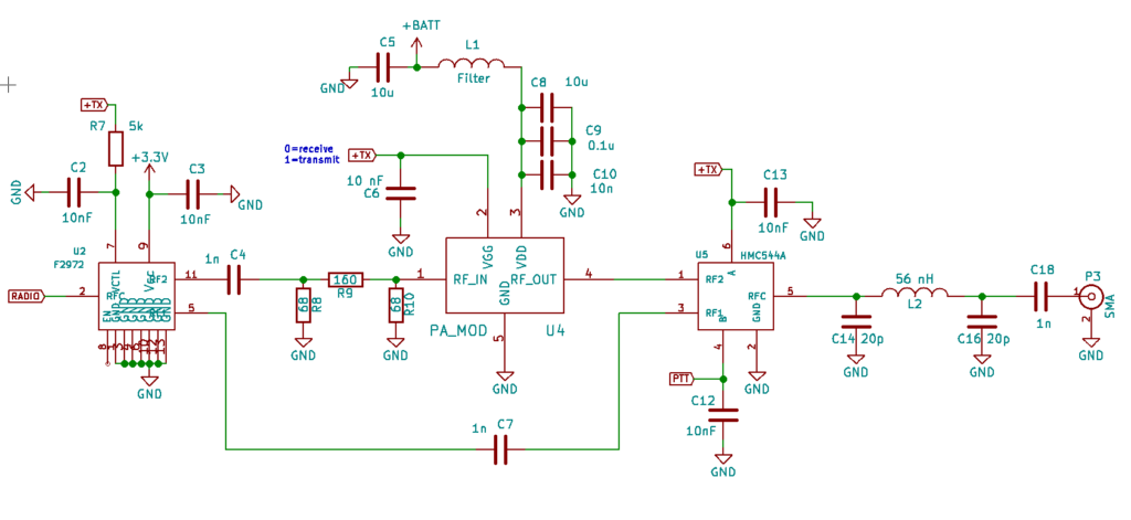
(Add 17. july 19) Schematic for the PA. The output of the radio module is 0.5W and must be attenuated. Two switching modules (U2 and U4) bypasses the PA module in receiving mode. There is also a pi-filter (low-pass) between the PA and the antenna.
Comments
5 responses to “Second round of tracker project”
Could you please share the part number of the RF switch? I am thinking of building a device with a similar PA (though a different transceiver). The only easily available part I could find is SKY13290, but the package seems very small and not easy to work with.
Thanks,
Artur M0AGX
It is two RF switches actually. One F2972 for input to the PA module (U2) and one HMC544A for output to the antenna (U5). The F2972 is a very small package and is not easy to mount. By carefully using a heat gun and after some practising I can do it. The F2972 has higher isolation and the HMC544 can handle more power, though I suspect it is pushed to its limit (the datasheet says that max input power is 39 dBm which is 8 watts when control voltages are 5V).
Really impressive work!
It is also very appreciated that you have release the design under opensource.
I was looking for the electronic schematic, bill of materials and pcb files, but I could not find them. We would like to build these trackers to be used at our radio club for events where we have the task to track for example rally cars.
Do you plan to release the hardware design i near future?
73, Patrik SA3PJN
Cool to hear that you’d like to build trackers. I can of course help and share the schematic and PCB files. I use KiCad. Let me take a look at it since there is some time since I worked on it.. I can send u the files and also share them on Github. There are maybe also some small improvements to be done on the PCB.
There is another project in Norway (The Polaric Tracker) that adopts some of the ideas and uses a ESP32, but I have not been involved in this until now. It will need some more time to be ready, and the hardware design will probably not be open source. Maybe it will use some of my software. I am also considering to make a new version of Arctic Tracker without the 5W PA, but with a LoRa module to function as a APRS/LoRa tracker and gateway..
73. LA7ECA, Øyvind
Süper nice
Pcb dizayn and schematic send me please
+905052108146 WhatsApp
[email protected]