The Arctic Tracker project is not dead (yet). The idea is to develop a tracker device with traits like these:
- It is modular, it can be assembled mainly from existing modules. Should be fairly easy to assemble.
- It has plenty of computing room and is open source. It can be a platform for hacking and innovation.
- In addition to VHF radio using APRS protocol, it can communicate over the internet.
- It can store tracking data for later uploading using internet.
- It is affordable.
A scenario we would like to explore is that the tracker stores a position log with a lot higher resolution than it can transmit over an APRS channel. This log could be automatically uploaded to a server when the tracker is moving within a WIFI zone and connecting to the internet. A WIFI connection could also be used for easy configuration or the device could be used as an APRS IGATE. A WIFI zone could even be provided by a smartphone which can be an easy way to access the device from a smartphone app.
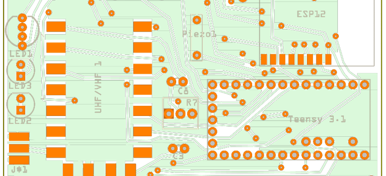
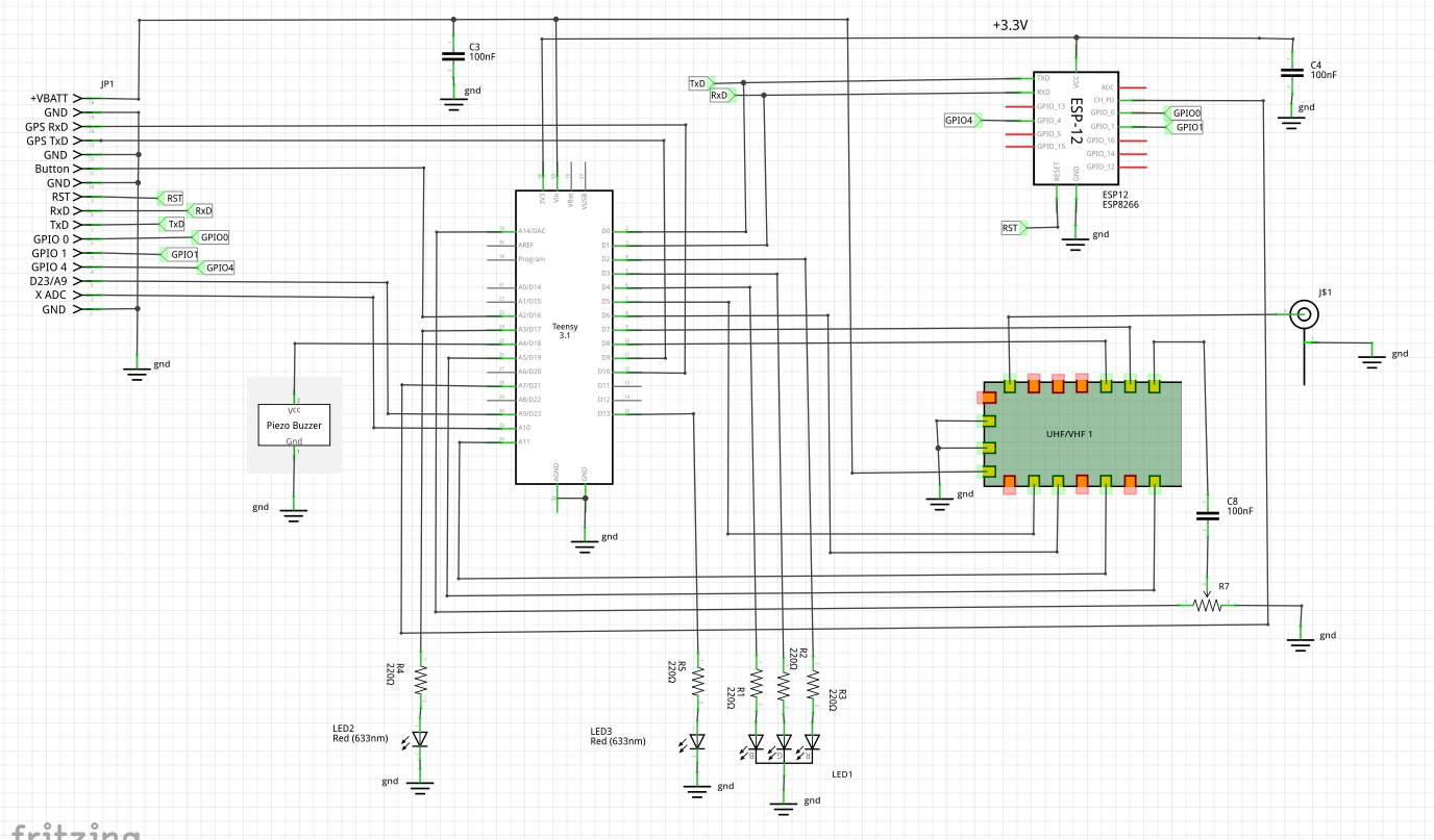
We are designing a prototype, or more correctly, a lab model to use for testing and further development. In addition to the VHF radio module we plan to use two microcontroller modules:
- A Teensy 3.2 as a the main controlling unit. It handles GPS data and APRS signalling, with a RTOS (ChibiOS/RT) and custom firmware written in C (partly based on earlier work on Polaric Tracker). See earlier posts on this.
- A ESP-8266 WIFI module with a 32 bit MCU (ESP-12). It is connected to the main (Teensy) MCU over a serial line. It is used to connect to the internet. It may also be used for storage since it has 4 MB flash memory and (possibly) a simple file system.
A candidate firmware for the ESP module is NodeMCU which offers a scripting language (LUA) and a file system. Other firmware may be considered (using Python or Javascript), but NodeMCU seems to be the most mature. Alternatively one could write a custom firmware in C or C++. It may offer better performance but it is a lot more work to hack and debug.
A PCB board is now in production, where the the most important parts can be mounted. It is just a first shot. It is not meant to be complete or free of mistakes. There will be a buzzer, 3 leds (one RGB led), antenna connector, a connector for battery, GPS, testing, etc.


Comments
One response to “Designing a lab model”
I mentioned that it could be accessed from a smartphone or a web-browser. This is the preferred way to add a display and a more advanced user interface to the tracker.
However, I still consider adding a cheap LCD display to the tracker hardware. At least as a option. Why? It will allow us to show important info like IP-address, callsign, battery status, if the tracker is tracking, etc. A simple menu can be added to select between some actions and options. Internet on/off, digipeater on/off for example.
Still, the tracker must be robust, and simple and intuitive to use.
Bluetooth? Well, it could also be an option. Wifi may be simpler to use, but may also use more power. However, a bluetooth module adds somewhat to the total cost and complexity of the device.
Any thoughts on this?