
The documentation for the Yaesu DR-1X repeater has a number of shortcomings. This post will describe my findings so that others may hopefully benefit from my research.
In our current application we are interfacing two of these repeaters, each connected to a separate USB sound interface and RS-232 serial port for squelch and PTT signaling. In the future I hope to spin a complete USB interface board with both sound and GPIO signaling.
Be aware that so far we have fixed the repeater’s TX mode to FM. We have not yet tested any of this in “Auto” TX mode. RX mode is Auto.
Let’s talk about the squelch and PTT signaling first.
The simplest part, perhaps, is the PTT. In the documentation for the PTT (pin 2), the owners manual informs:
When this pin is pulled low by an external device, it keys the repeater transmitter.
When I first tried this, nothing happened. In fact, this only works if you put the repeater in “Remote mode” by also pulling low the “EXT I/O” (pin 1).
In remote mode the repeater becomes nothing more than a big expensive transceiver, and does not on its own repeat signals received on RX radio. This has the additional drawback of not triggering the repeater’s internal ID system. More on this in a later post.
The repeater has two squelch outputs. “SQL DET” is pin 4 and is described:
This is an open-collector, active-low output capable of sinking about 10 mA. It indicates that the receiver squelch is open.
Indeed this signal is pulled low whenever the noise squelch is open, which makes it the wrong signal to use in this case.
Pin 3, on the other hand, is pulled low in the same way as pin 4. This also seems to be an open-collector output, active-low, though the documentation does not clarify this. We tested this pin with the repeater in Auto RX mode, and this pin is pulled low on both correct CTCSS tone, and a valid C4FM digital audio signal. It is worth mentioning, though, that there seems to be a clamping mechanism on this pin. If pulled towards the 12 volt rail with a pull-up resistor, the voltage will stop around 5 volts. I guess there is something like a 5.1 v zener protection diode in there to limit the voltage on the collector output.
This is the schematic of how I have interfaced PTT and squelch on the DR-1X repeaters to an RS-232 serial port.

Then there’s the audio.
The received audio is really simple. We fed the AF OUT (pin 9) to the input of our USB sound interface. Gain is so far adjusted using the sound interface internal mixer. The pin lets out regular analog audio even when someone is transmitting digital C4FM to the repeater. This is really handy for us in this application.
Transmit audio is worse. There is the AF IN (pin 7). Its description in the manual leads you to think it’s nice to use. Among other things it says:
Valid during external PTT control
Now, read the documentation for pin 2 again:
On signaling while controlling the external PTT:
  Pin 6 (TONE IN) ... Valid
  Pin 7 (AF IN) ... Invalid
So, we need to use TONE IN (pin 6). When the repeater is in remote mode and keyed, it does not generate the configured CTCSS subtone. Feeding the USB sound straight into the repeater also sounds too dark and the level is too low. Is this pin a direct modulator input?
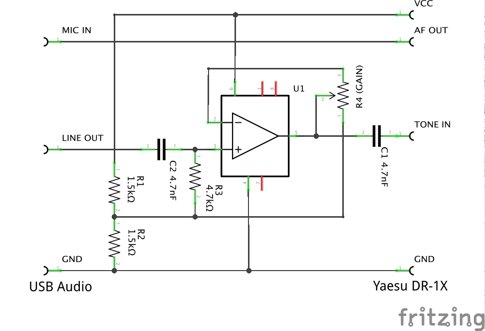
We solved this by having our interface software in the computer generate the subtone mixed with the audio, and we made an adjustable gain high-pass filter stage for feeding the audio into the repeater.
Schematic:
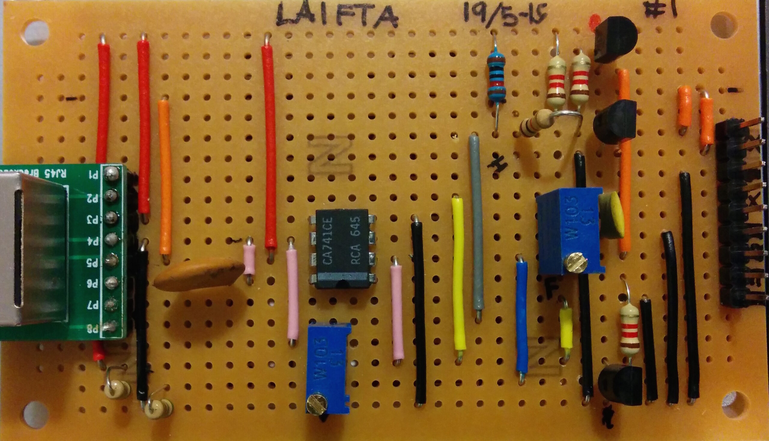
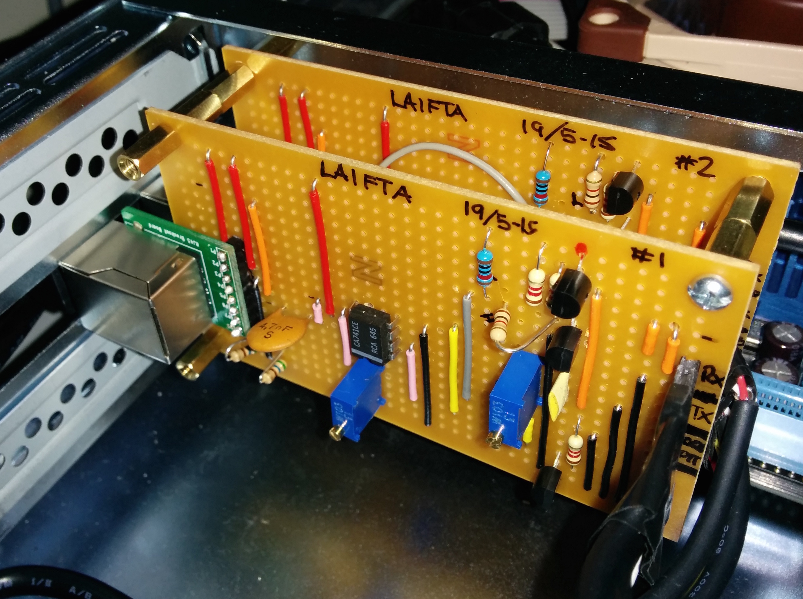
These two circuits have been combined on a stripboard, and the result was duplicated. The two boards were mounted in our control computer which links the repeaters to eachother, in addition to the Echolink network.
Details on the software setup will be available in a later post.
Comments
4 responses to “Interfacing the DR-1X Repeater”
Excellent Articles – but what are the identifiers of the components used? Is line isolation required on the audio side?
Thanks! The gain stage uses a general rail-to-rail capable opamp with components around it to roughly match the audio impedances. Line isolation has not been an issue.
Our current setup uses ATmega32u4 (Arduino “Pro Micro” clones) to sequence the different keying lines on the repeater to try to work around some of the firmware issues. Could be the newest firmware does not need this anymore.
Finally we went with a separate subtone encoder on TONE IN, and sending the audio from TheLinkBox into AF IN. This gives us a very stable result with good audio.
I see that U1 in diagram 2 is a 741. I see that there are a few possible errors in the sound card interfacing diagram – the 741 is powered through Pin 7 and the output is via Pin 6. Pins 1, 5 and 8 should be free. The pot (unlabelled) also is 10K (103).
On the subject of trimpots – I note that there are 2 in the picture of the actual implementation yet only one referenced in both diagrams.
Yes, the schematic is probably wrong. Sorry about that. The setup ended up being quite different from what is outlined here. We use a MCU to sequence the keying pins, and a separate subtone encoder on TONE IN. Audio goes to AF IN.
Instead of powering the interface from the repeater side (12v), we’re powering it using USB 5v from the computer. This lets the repeater operate freely if the computer goes down.
The LM741 is unusable in this setup since it is not rail-to-rail capable. Cannot remember right now which op-amp we ended up using, but it is sort of a temporary setup until we can implement the MMDVM project along side this analog capability.